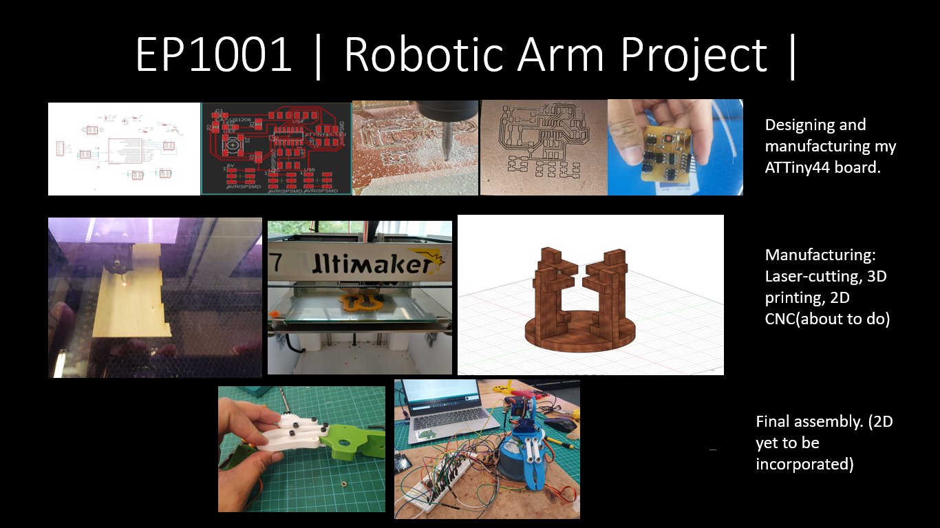
Presentation Slide
Bill of Materials
- 2 MG996R Continouous Servos
- 2 SG90 Servos
- 4 10k Ohm Potentiometers
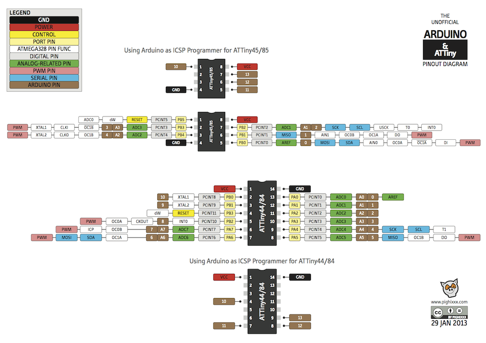
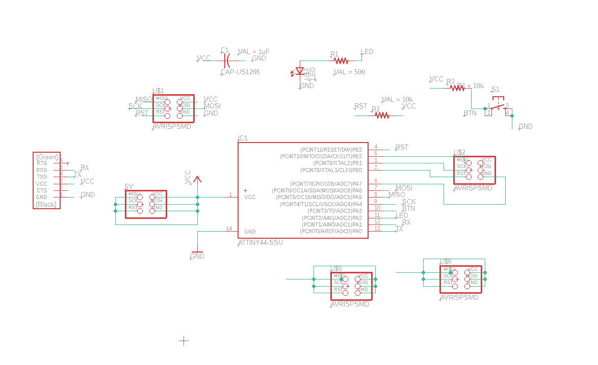
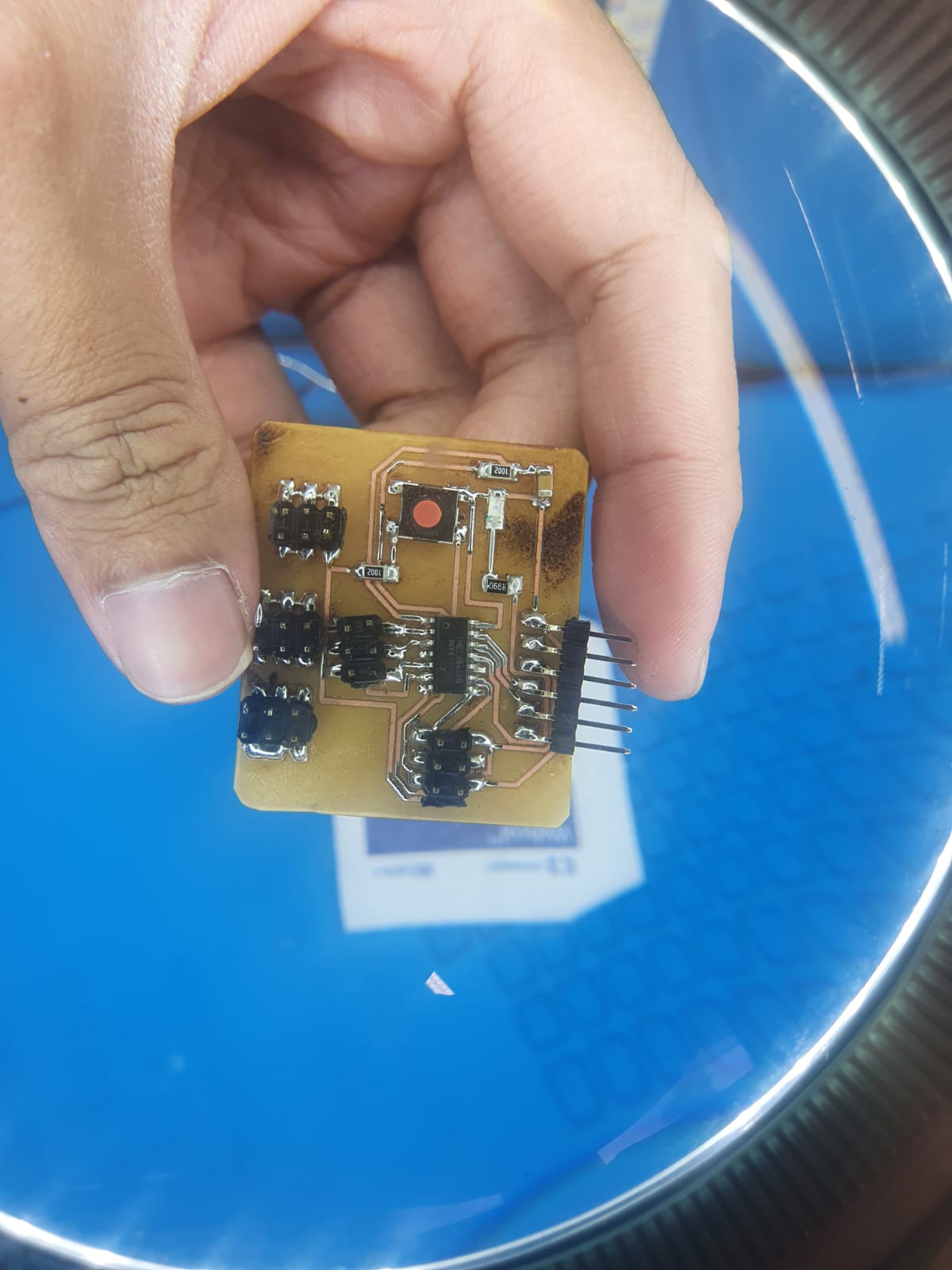
Microcontroller Used: ATTiny44
The reason why I chose to use the ATTiny44 board was becaused I needed 4 PWM ports for my servo motors which is just sufficient as well as at least 4 analog ports for theinput data from the potentiometers.
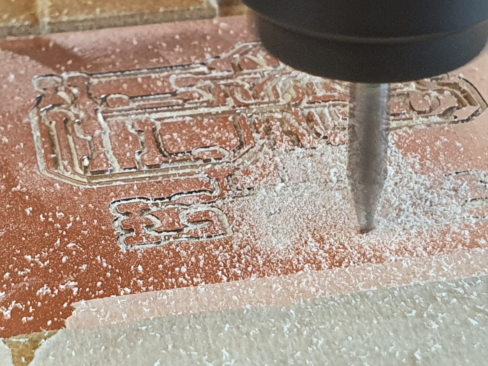
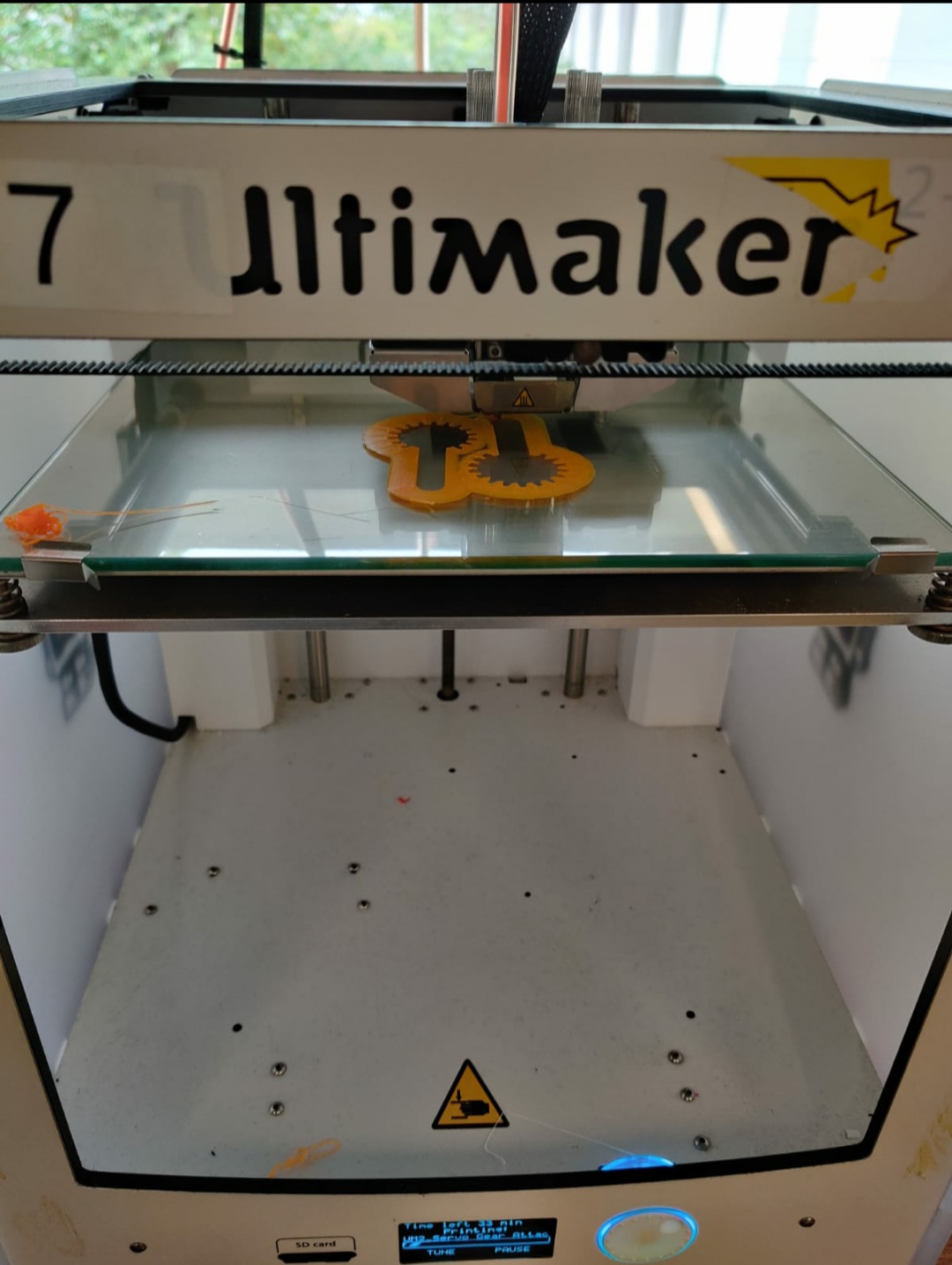
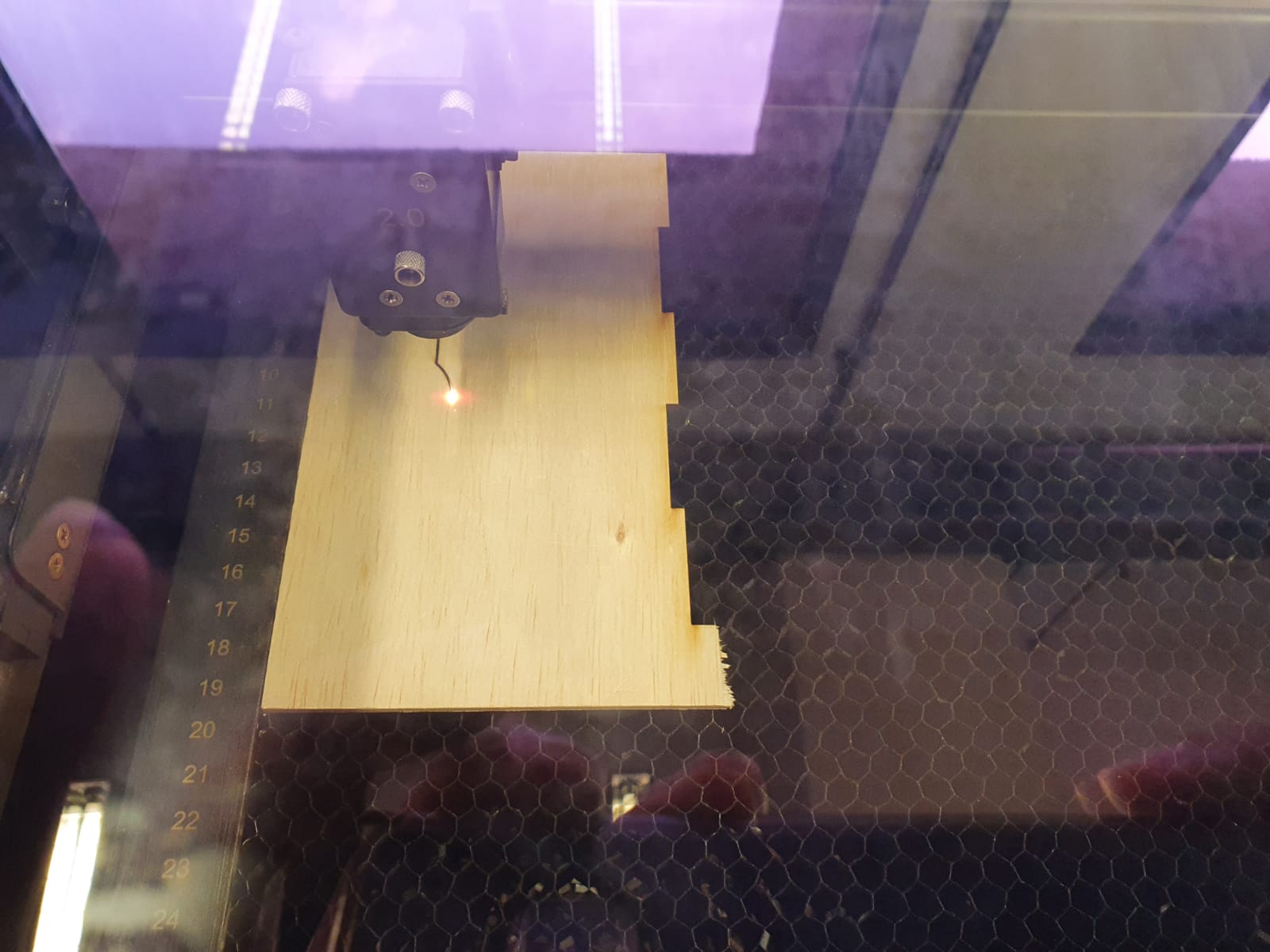
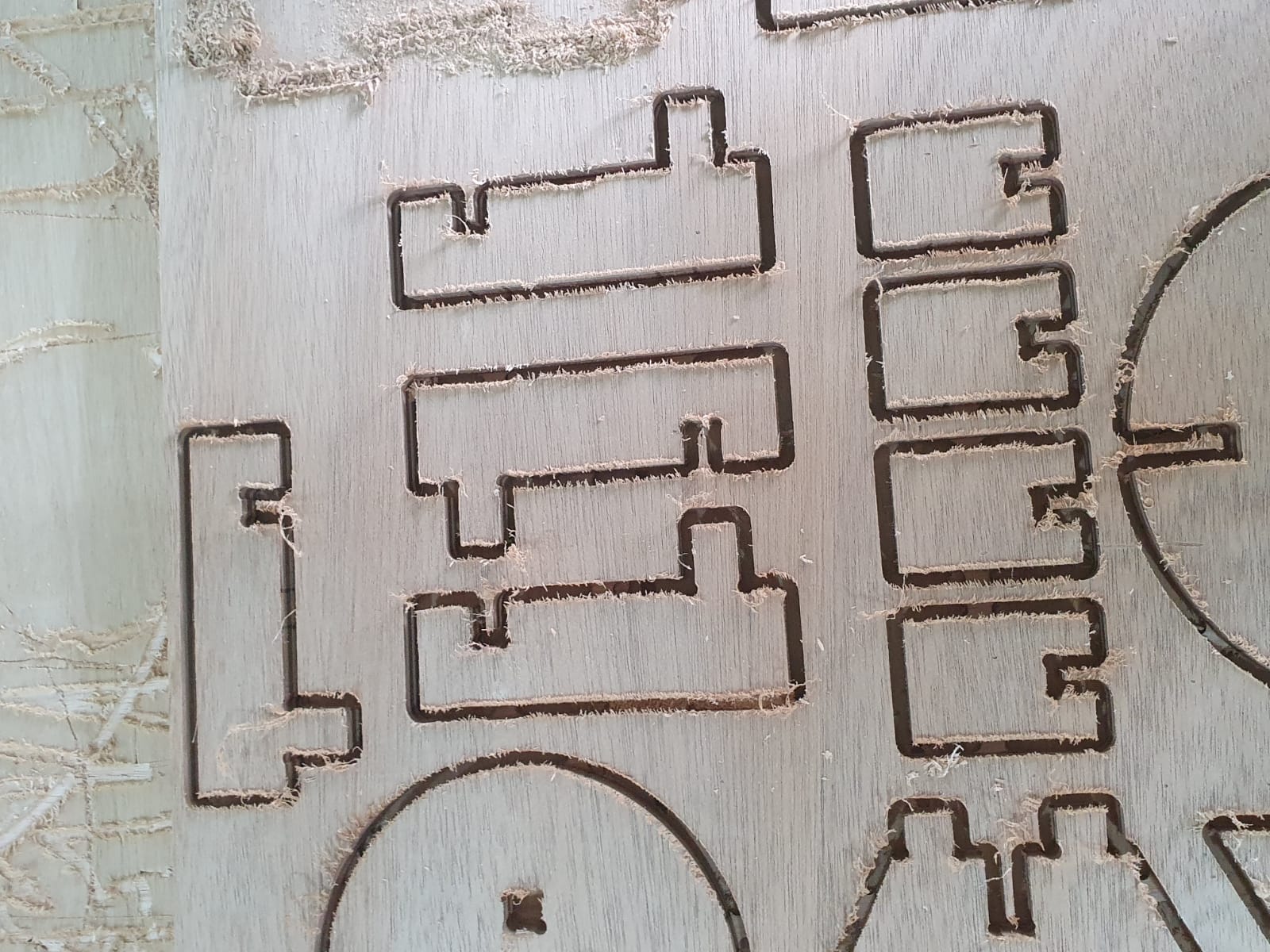
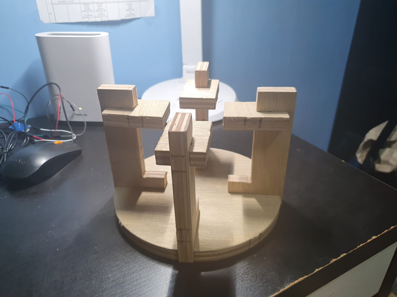
Manufacturing Process
I did laser cutting, 3D printing and 2D CNC.
Programming
I used Arduino IDE for programming. Below is the code I've written for my program.
/*
 Controlling a servo position using a potentiometer (variable resistor)
 by Michal Rinott <http://people.interaction-ivrea.it/m.rinott>

 modified on 8 Nov 2013
 by Scott Fitzgerald
 http://www.arduino.cc/en/Tutorial/Knob
*/

#include <Servo.h>

Servo myservo;  // create servo object to control a servo
Servo myservo1;  // create servo object to control a servo
Servo myservo2;  // create servo object to control a servo
Servo myservo3;  // create servo object to control a servo

int potpin = 0;  // analog pin 0
int val;    // variable to read the value from the analog pin

int potpin1 = 1;  // analog pin 1
int val1;    // variable to read the value from the analog pin

int potpin2 = 2;  // analog pin 1, LED
int val2;    // variable to read the value from the analog pin

int potpin3 = 4;  // analog pin 1, BOTTOMCENTER
int val3;    // variable to read the value from the analog pin


void setup() {
  myservo.attach(7);  // attaches to Arduino pin 7 PWM
  myservo1.attach(8);  // attaches to Arduino pin 8 PWM
  myservo2.attach(6);  // attaches to Arduino pin 6 PWM , TOPCENTER
   myservo3.attach(5);  // attaches to Arduino pin 5 PWM , BOTTOMLEFT
}

void loop() {
  val = analogRead(potpin);            // reads the value of the potentiometer (value between 0 and 1023)
  val = map(val, 0, 1023, 0, 180);     // scale it to use it with the servo (value between 0 and 180)
  val1 = analogRead(potpin1);            // reads the value of the potentiometer (value between 0 and 1023)
  val1 = map(val1, 0, 1023, 0, 180);     // scale it to use it with the servo (value between 0 and 180)
  val2 = analogRead(potpin2);            // reads the value of the potentiometer (value between 0 and 1023)
  val2 = map(val2, 0, 1023, 0, 180);     // scale it to use it with the servo (value between 0 and 180)
  val3 = analogRead(potpin3);            // reads the value of the potentiometer (value between 0 and 1023)
  val3 = map(val3, 0, 1023, 0, 180);     // scale it to use it with the servo (value between 0 and 180)


  myservo.write(val);                  // sets the servo position according to the scaled value
  myservo1.write(val1);                  // sets the servo position according to the scaled value
  myservo2.write(val2);                  // sets the servo position according to the scaled value
  myservo3.write(val3);                  // sets the servo position according to the scaled value
  delay(30);                           // waits for the servo to get there
}
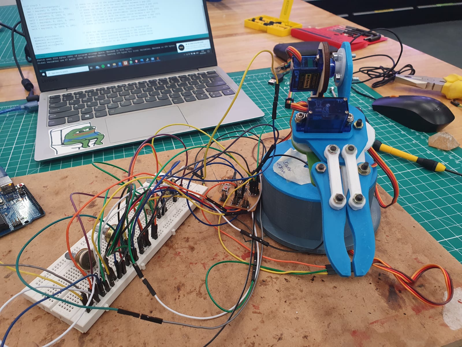
Final Product
Reflection of the project
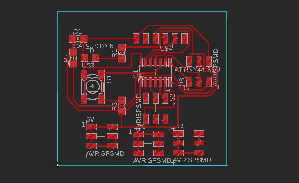
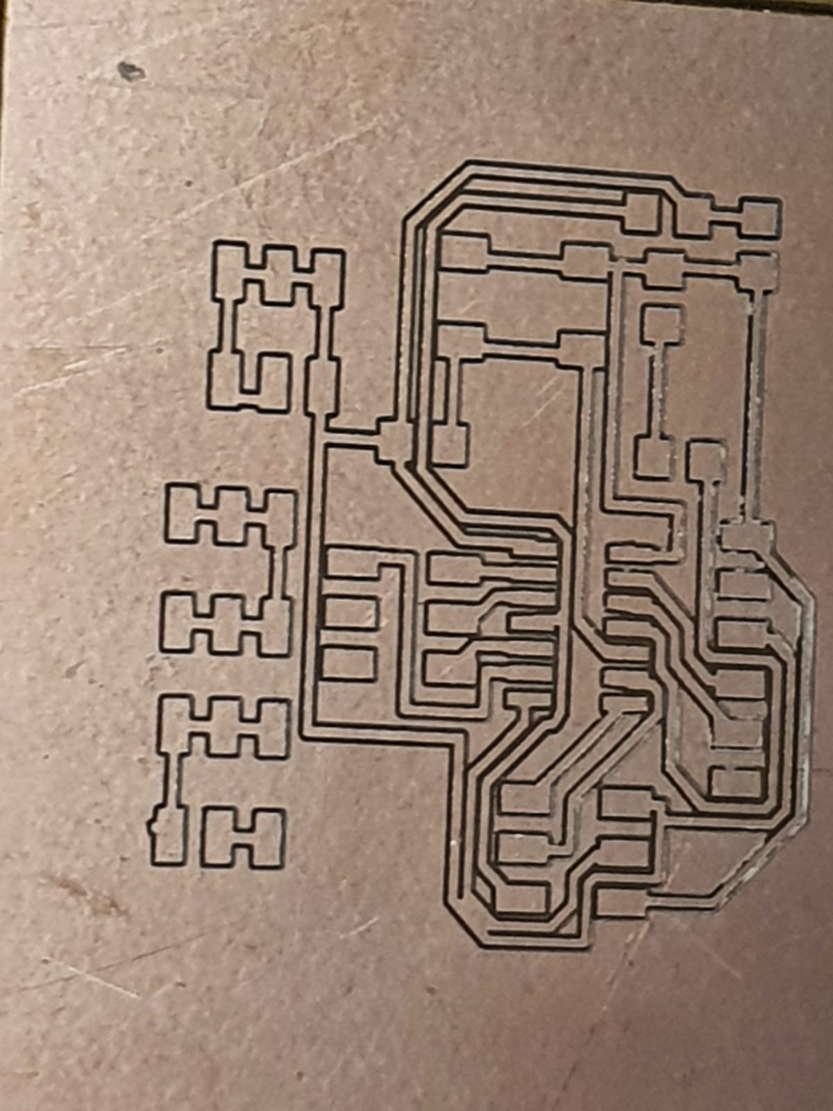
Challenges faced: One challenge I faced was selecting, desigining and making the PCB. My initial idea of the project was to create a 6-axis, Robotic arm. I
created my Attiny44 board successfully. However, when I tried to upload my project code into the microcontroller, thre wsa an error message saying that there was not
enough memory space in microcontroller and that my code was too long. Hence, I decided to tweak my project by creating a 4-axis robotic arm controlled with potentiometers.
Finally, my project could be executed.
What I learnt: I should have checked if my code was working on the dual in line package first before I decide to use the smd version.