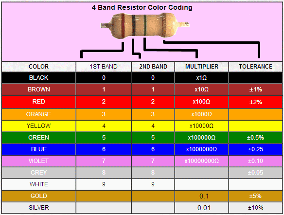
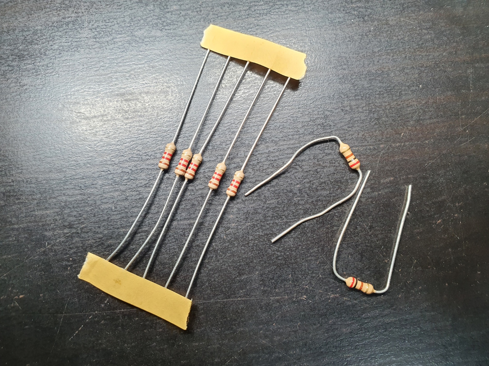
Resistors: Controls the amount of current following through the circuit. Literally, provides resistance. Helps in
preventing a surge of current which may spoil an electrical component.
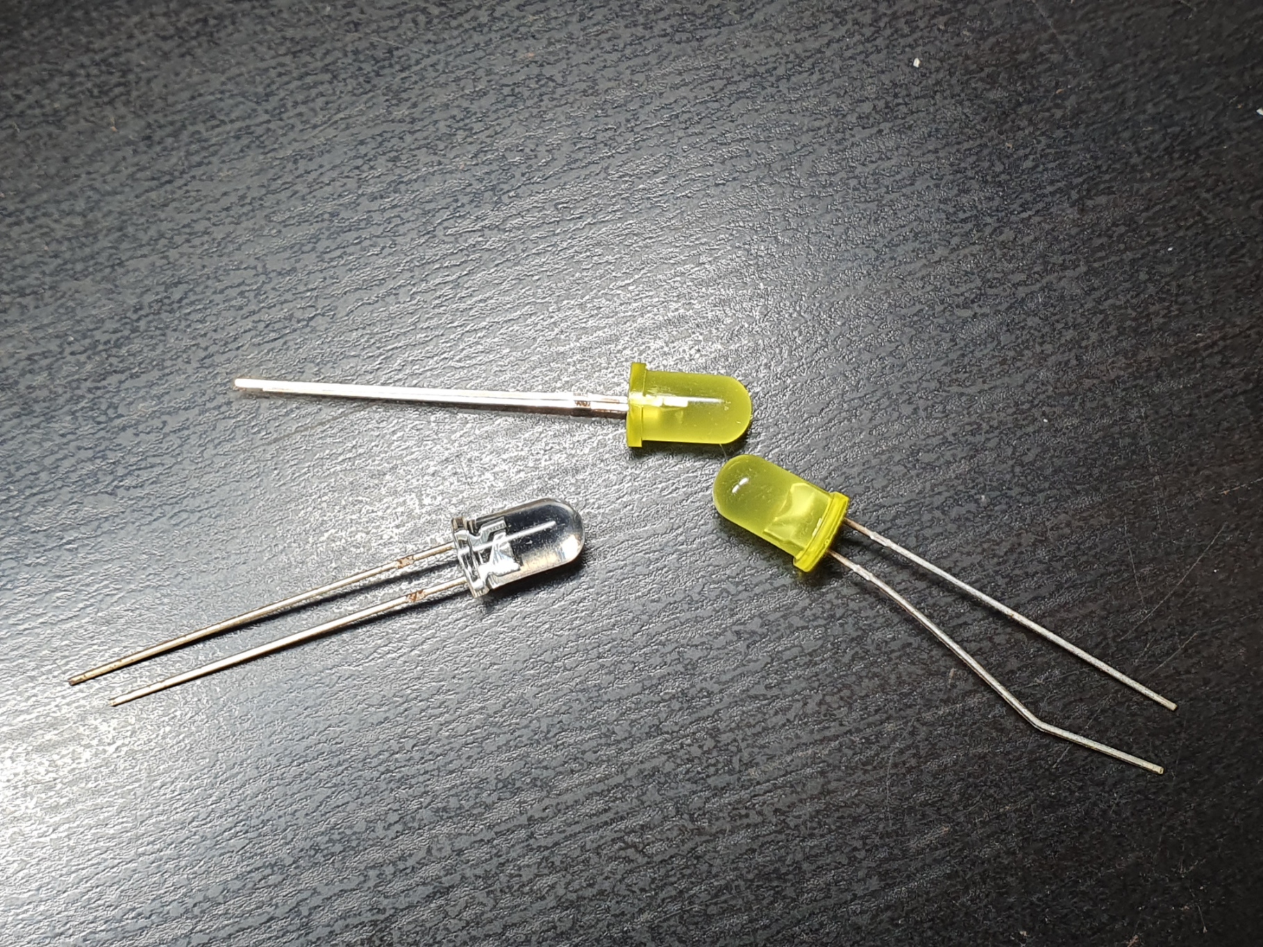
Diodes: Allows current to flow through one direction only. Used to rectify AC currents.
D.C Current: A constant direct supply of current in one direction. Produces a straight line waveform.
A.C Current: An alternating supply of current in 2 directions. Produces a sin waveform.
Transistors: Transistors allow a small current to control or amplify a larger current. It also can act as a switch.
Potentiometer: A variable resistor. Unlike a fixed resistor a potentiometer allows the user to alter
its resistance to reach its desired level by changing the length of the resistor strip inside.
Short-circuit: An unintended path travelled by excessive current due to low resistance/impedence. Example; Live wire touching the
Ground wire.
Open-cicuit: Happens when there is an 'gap' circuit. Resistance (or air) is too high for current to flow through. Typically
happens when you turn off the switch.
As a basic rule of thumb, current will travel in the path of least resistance.
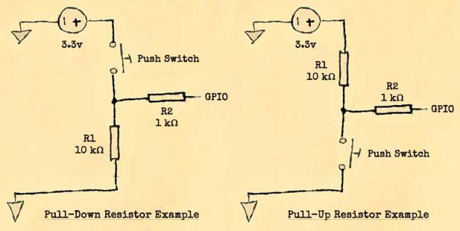
For the Pull-down resistor, the swtich placed before the junction that connects R2 and R1. When the switch is open,
no current flows through the circuit. Thus, initial state of the input port is 0 or LOW. If the switch is closed, current flows through the
R2 branch as R2 is less than R1. The state of the input port will become 1 or HIGH.
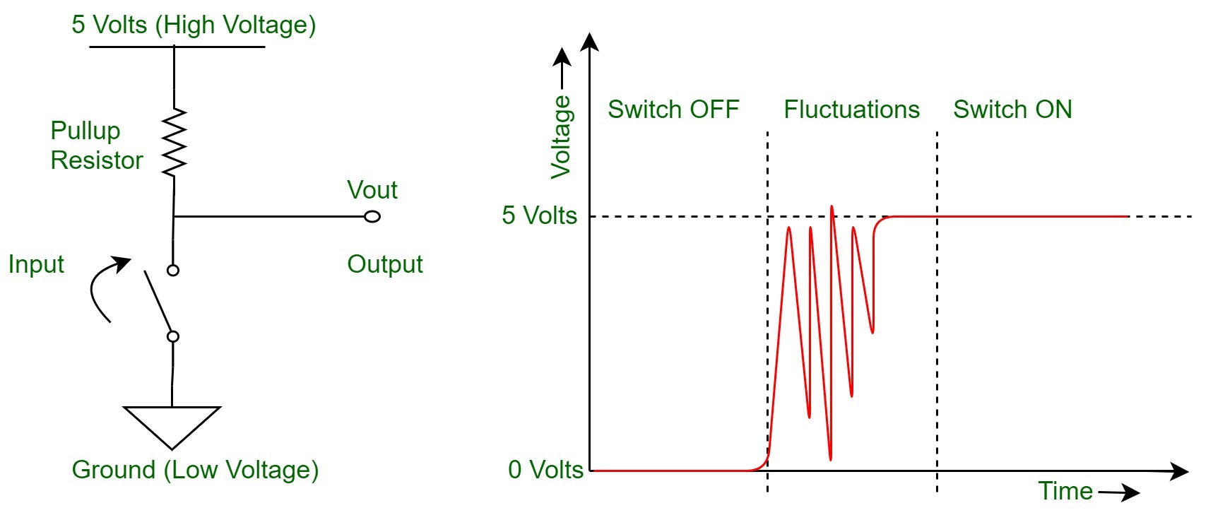
For the Pull-up resistor, the swtich placed after the junction that connects R2 and R1. When the switch is open,
current flows through R1 and R2 to the input port. Thus, initial state of the input port is 1 or HIGH. If the switch is closed,
current flows through the path of least resistance and directly to the ground. Thus, final state of the input port is 0 or LOW.
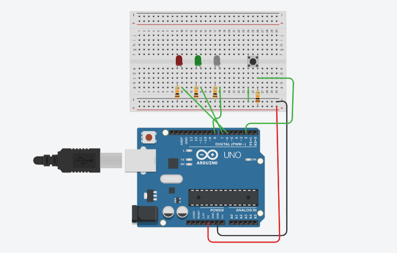
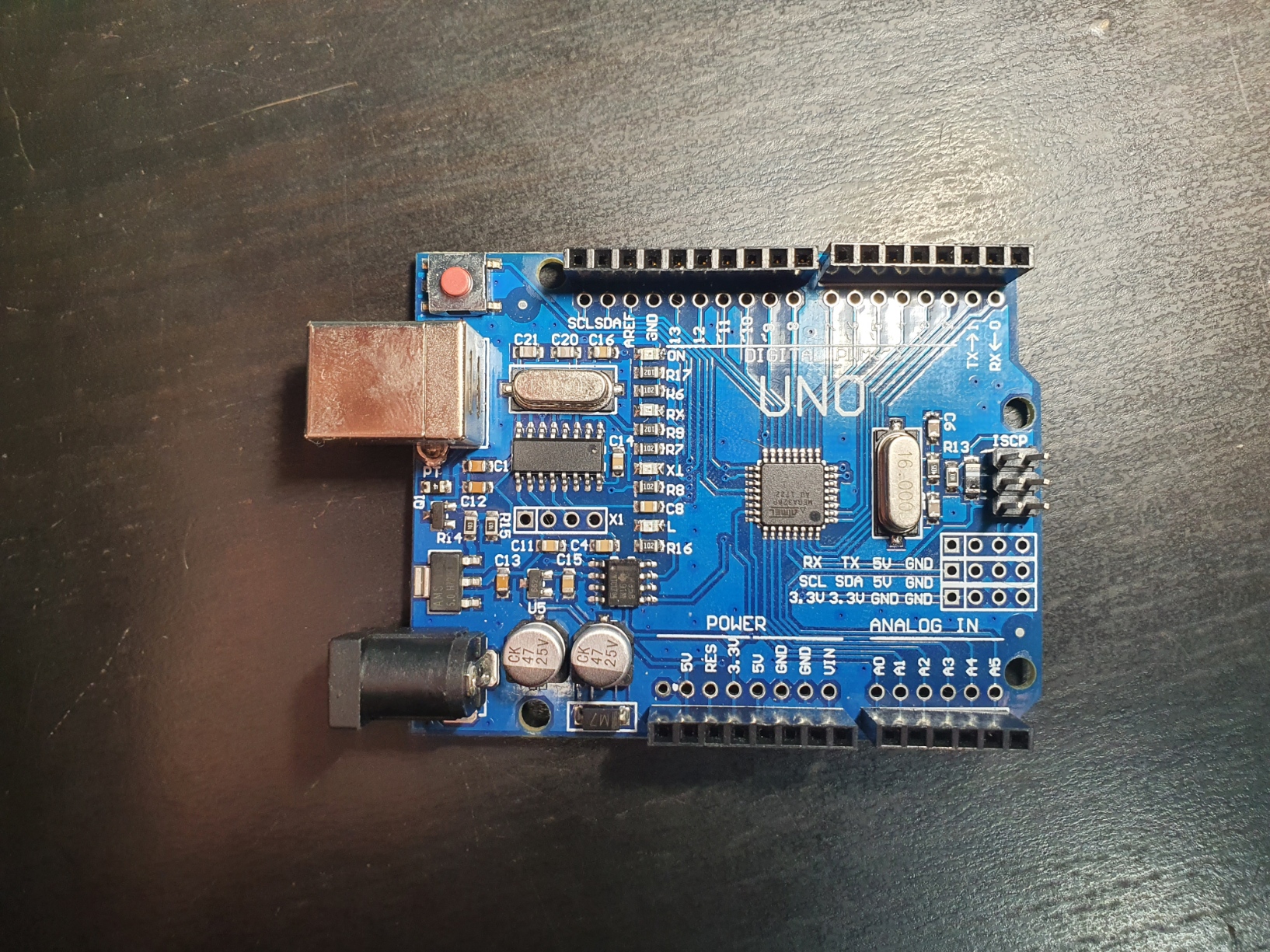
Personally, I test out my Arduino circuit on TinkerCAD first
before building the actual circut.
Using a pull-up resistor of 10k (Brown, Black, Orange, Gold),
initially, LEDs are all in the OFF state.
pressing the switch, turns on only the RED LED.
pressing the switch again, turns on only the GREEN LED
pressing the switch again, turns on only the WHITE LED
pressing the switch again, turns on all LEDs
pressing the switch for longer than 3 seconds, turns off all LEDs returning to the initial state.
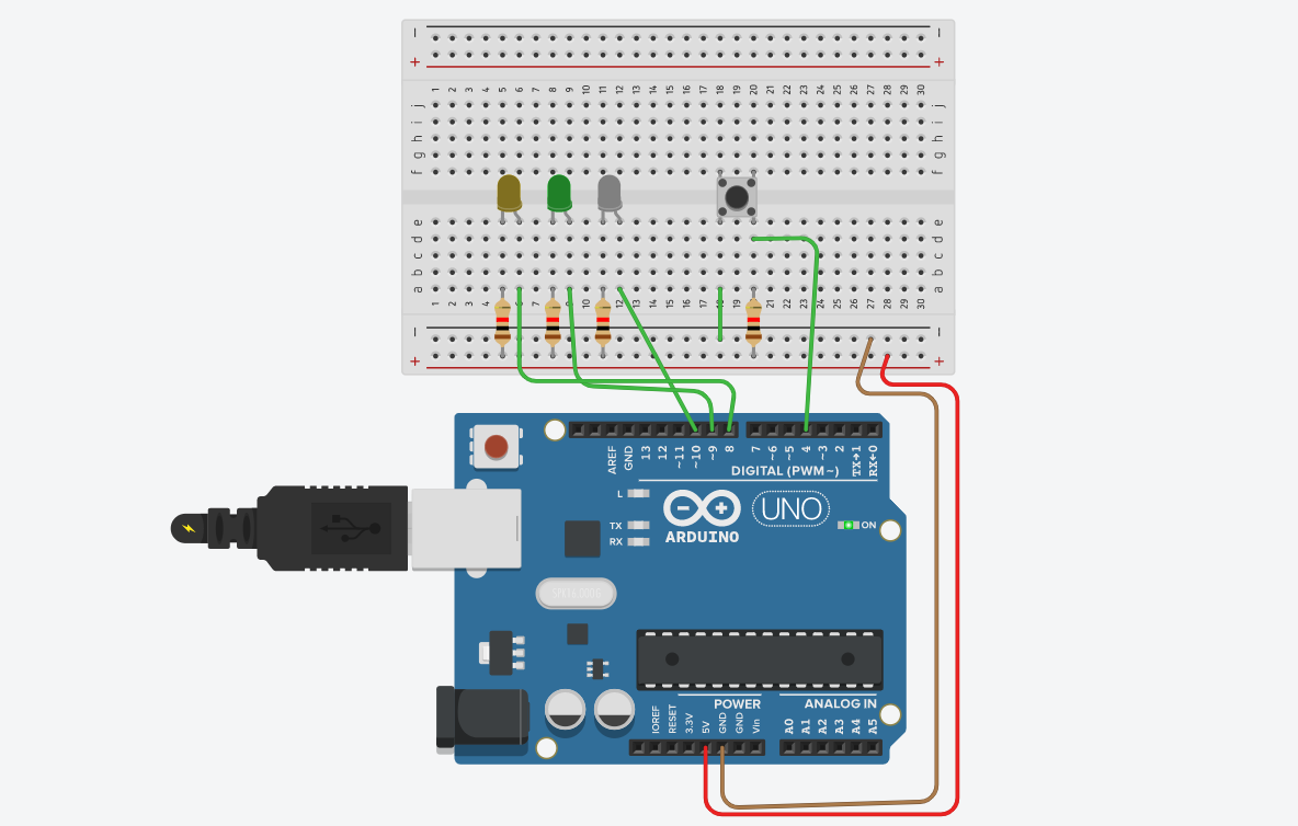
As per intructions, I have also connected the RED, GREEN and WHITE LEDs to output port 6, 7 and 8 respectively.
I have coded the Assignment 12 circuit in 2 ways. (Click to download code)
Note that the red LED is rather small and blocked by the wire :/
Debouncing
Pushbuttons often generate spurious open/close transitions when pressed, due to mechanical and physical issues:
these transitions may be read as multiple presses in a very short time fooling the program. Without debouncing, pressing the button once
may cause unpredictable results. Debouncing therefore helps in filtering out the unwanted signal.
Delay vs. Millis
The delay() function and millis() function are similar by making the programme "wait". The difference is delay() function pauses
the programme as specified in the parameter and does not allow for intermediate actions to be carried out
while the millis() along with if statements allows for actions to be carried out whilst
waiting. Think of millis() as a stopwatch. If the stopwatch does not satisfy the specific time, action will not be carried out.
For basic programmes, both functions can be used interchangebly but as the programme increases in complexity millis() is preferred
as it increases accuracy and is more versatile.
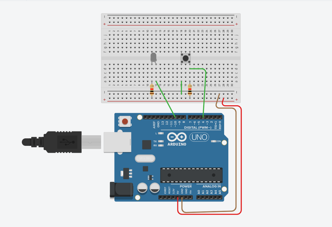
We can apply debouncing and millis() concepts to toggle a single or multiple LEDs. To toggle a single LED connect your circuit as follows |
Arduino Code: Toggle Single LED)
To toggle multiple LEDs, connect you circuit as follows | Arduino Code: Toggle Multiple LED
